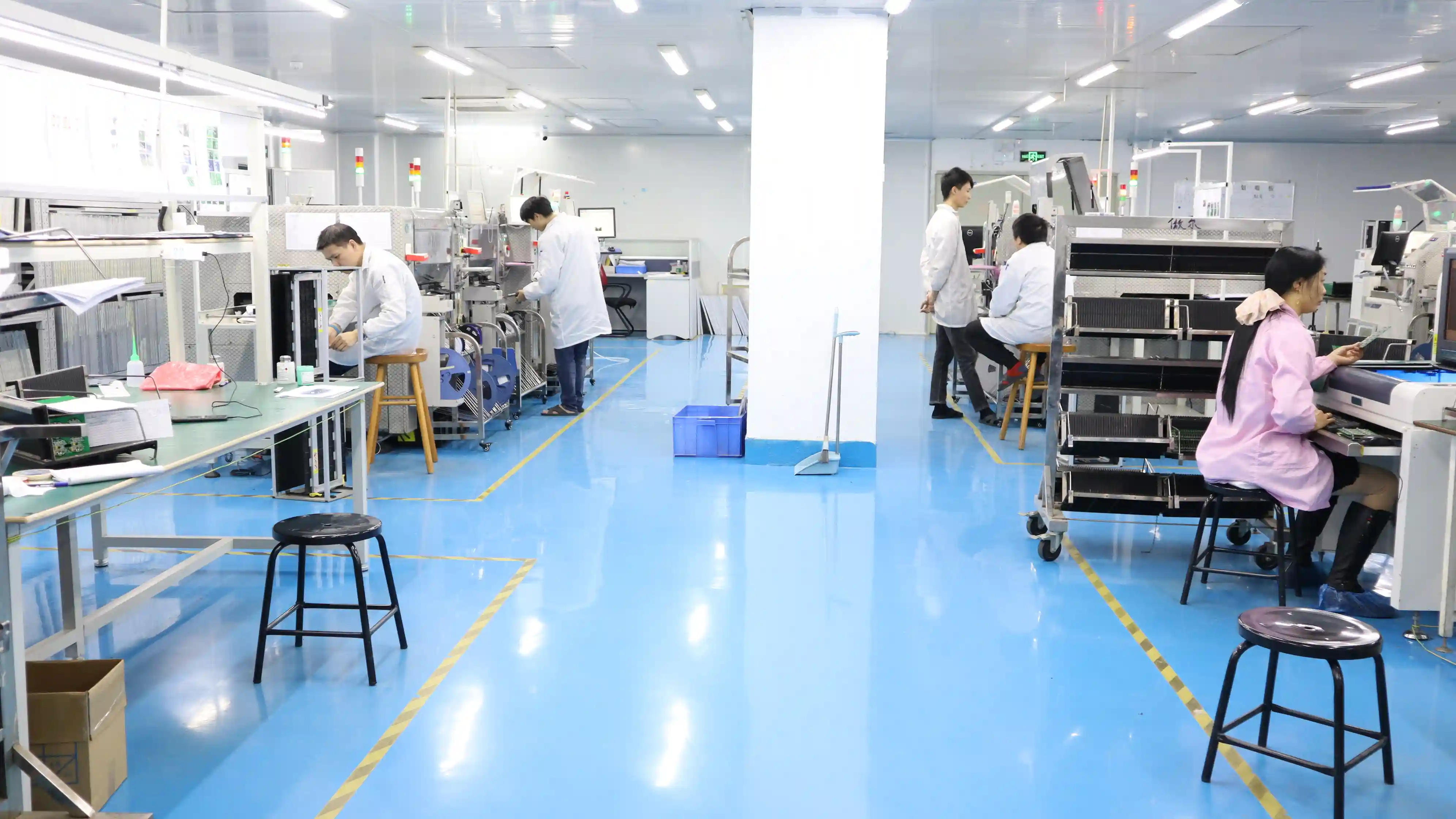
Fabrikanten15 min
Top 10 PCB Fabrikanten 2026: Complete Gids
Uitgebreide vergelijking van de beste PCB-fabrikanten. Van JLCPCB tot Eurocircuits - ontdek welke fabrikant bij uw project past.
 Hommer Zhao|16 Dec 2024
Praktische artikelen van onze engineers. Leer alles over PCB ontwerp, productie en assemblage - direct uit de fabriek.
Met meer dan 15 jaar ervaring in PCB productie en elektronica assemblage, richtte Hommer WellPCB op met een missie: Europese bedrijven toegang geven tot hoogwaardige, betaalbare PCB-oplossingen. Als elektrotechnisch ingenieur begrijpt hij zowel de technische eisen als de zakelijke uitdagingen van inkopers.
U vraagt zich af: waarom niet gewoon lokaal inkopen? Hier zijn 6 redenen waarom honderden Nederlandse en Belgische bedrijven voor ons kiezen.
Geen tussenhandel, geen importeurs. U koopt rechtstreeks bij de fabrikant. Tot 40% voordeliger dan Europese leveranciers.
Prototype in 24u productie + 3-5 dagen DDP levering. Vaak sneller dan 2-3 weken wachttijd bij EU-fabrikanten.
PCB + Assemblage + Kabelbomen + Box Build. Eén aanspreekpunt, één factuur, geen coördinatie tussen leveranciers.
ISO 9001, IATF 16949, ISO 13485, UL. Dezelfde certificeringen als Europese fabrikanten, geauditeerd door internationale bureaus.
Uw vaste accountmanager spreekt uw taal. Geen taalbarrière, directe communicatie, reactie binnen 1 uur.
NDA standaard, DDP levering (wij regelen invoer), gratis DFM check, 100% kwaliteitsgarantie met gratis herproductie.
Uitgebreide vergelijking van de beste PCB-fabrikanten. Van JLCPCB tot Eurocircuits - ontdek welke fabrikant bij uw project past.
Hommer Zhao|16 Dec 2024
Complete vergelijking tussen rigide en flexibele printplaten. Kosten, toepassingen en ontwerptips voor beide types.
Hommer Zhao|15 Dec 2024
Surface Mount vs Through-Hole technologie uitgelegd. Voor- en nadelen, kosten en wanneer welke methode te kiezen.
Hommer Zhao|14 Dec 2024Uitgebreide vergelijking van de beste PCB-fabrikanten. Van JLCPCB tot Eurocircuits - ontdek welke fabrikant bij uw project past.
Complete vergelijking tussen rigide en flexibele printplaten. Kosten, toepassingen en ontwerptips voor beide types.
Surface Mount vs Through-Hole technologie uitgelegd. Voor- en nadelen, kosten en wanneer welke methode te kiezen.
De meest voorkomende PCB-ontwerpfouten die ik in 15 jaar productie heb gezien. Bespaar geld en tijd met deze tips.
Welk PCB-materiaal past bij uw toepassing? Complete vergelijking van eigenschappen, kosten en toepassingsgebieden.
Wanneer kiezen voor Chinese of Europese PCB-productie? Kosten, kwaliteit, levertijd en risico's eerlijk vergeleken.
De beste EDA-tools vergeleken op prijs, functies en gebruiksgemak. Van gratis tot professioneel - vind uw perfecte match.
Kies tussen 2-laags en meerlaags PCB. Kosten, signaalintegriteit en designoverwegingen uitgelegd.
High Density Interconnect uitgelegd. Microvias, blind vias en wanneer HDI echt nodig is voor uw project.
ISO 9001, IATF 16949, ISO 13485, UL en IPC uitgelegd. Welke certificeringen zijn essentieel voor uw fabrikant?